Why is the AASHTO Accreditation Important for Your Company?
Achieving AASHTO Accreditation is a significant milestone for any construction materials testing laboratory. It signifies a commitment to quality, competence, and compliance with nationally recognized standards. This accreditation is not just a badge of honor; it’s a critical factor that can influence project approvals, client trust, and overall business success.
What is AASHTO Accreditation?
The American Association of State Highway and Transportation Officials (AASHTO) Accreditation Program (AAP) formally recognizes laboratories competent in testing construction materials. Managed by AASHTO re:source, the program ensures that laboratories meet specific standards, including AASHTO R18 and relevant ASTM standards, through rigorous assessments and proficiency testing.
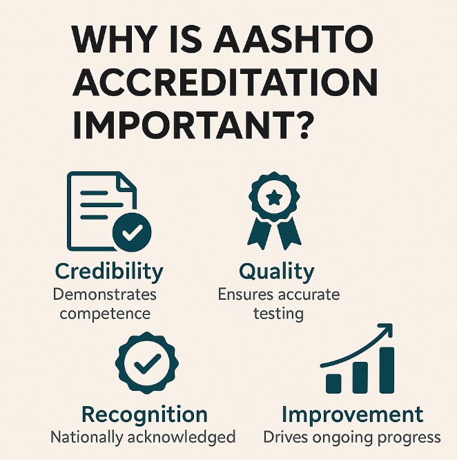
Why Does AASHTO Accreditation Matter?
1. Assurance of Quality and Competence
AASHTO Accreditation assures clients and stakeholders that a laboratory adheres to strict quality management systems and testing procedures. It demonstrates a lab’s commitment to producing reliable and accurate test results, which is crucial for infrastructure projects where material performance is paramount.
2. Regulatory Compliance and Market Access
Many state Departments of Transportation (DOTs) and federal agencies require AASHTO Accreditation for laboratories involved in public infrastructure projects. Without this accreditation, a laboratory may be ineligible to participate in certain projects, limiting business opportunities.
3. Competitive Advantage with an AASHTO Accredited lab
Accreditation differentiates a laboratory in a competitive market. It signals to clients that the lab meets high standards, potentially leading to increased trust, more contracts, and the ability to command premium pricing for services.

Step-by-Step Guide to Achieving AASHTO Accreditation
Step 1: Register Your Laboratory with AASHTO Resource
Begin by registering your laboratory with AASHTO re:source. This process involves providing basic information about your lab and the types of testing services you offer. Registration is the first formal step toward accreditation
Step 2: Develop a Quality Management System (QMS)
Implement a QMS that complies with AASHTO R18 standards. This system should document procedures, equipment calibration, personnel qualifications, and other quality-related processes. A robust QMS is the backbone of a successful accreditation.
Step 3: Schedule an On-Site Assessment
Request an on-site assessment through AASHTO re:source. During this visit, assessors will evaluate your laboratory’s facilities, equipment, personnel, and adherence to testing standards. They will identify any nonconformities that need to be addressed.
Step 4: Participate in the Proficiency Sample Program (PSP)
Enroll in the PSP, which involves testing standardized samples and submitting results for evaluation. This program assesses your laboratory’s testing accuracy and consistency compared to peer labs.
Step 5: Address Nonconformities
If the on-site assessment or PSP identifies any nonconformities, develop and implement corrective actions. Submit documentation demonstrating how these issues have been resolved to AASHTO re:source within the specified timeframe.
Step 6: Maintain AASHTO Accreditation
Once accredited, maintain compliance by:
- Continuously adhering to your QMS
- Participating in regular proficiency testing
- Undergoing periodic reassessments
- Keeping up-to-date with changes in testing standards
Real-World Impact: Case Study
Consider a laboratory in Houston, Texas, seeking to participate in state-funded highway construction projects. Without AASHTO Accreditation, the lab may be excluded from bidding on these projects. By achieving accreditation, the lab not only gains access to these opportunities but also enhances its reputation, leading to increased business from private sector clients who value accredited testing services.
AASHTO Accreditation is more than a certification; it’s a testament to a laboratory’s dedication to quality and excellence in construction materials testing. By following the structured accreditation process, laboratories can unlock new business opportunities, ensure compliance with regulatory requirements, and build lasting trust with clients.